Getting great 3D printing results isn’t just about having good equipment – it’s about designing parts that work well with the 3D printing process. Whether you’re new to 3D printing or looking to improve your results, these design tips will help you create parts that print successfully, look professional, and function as intended.
Understanding the 3D Printing Process
Before diving into specific design tips, it’s important to understand how resin 3D printing works. Unlike traditional manufacturing that removes material (like machining) or shapes material (like molding), 3D printing adds material layer by layer. This fundamental difference creates unique opportunities and constraints that should influence your design decisions.
Foundation Principles for 3D Printing Design
1. Design for Orientation
The Most Critical Decision
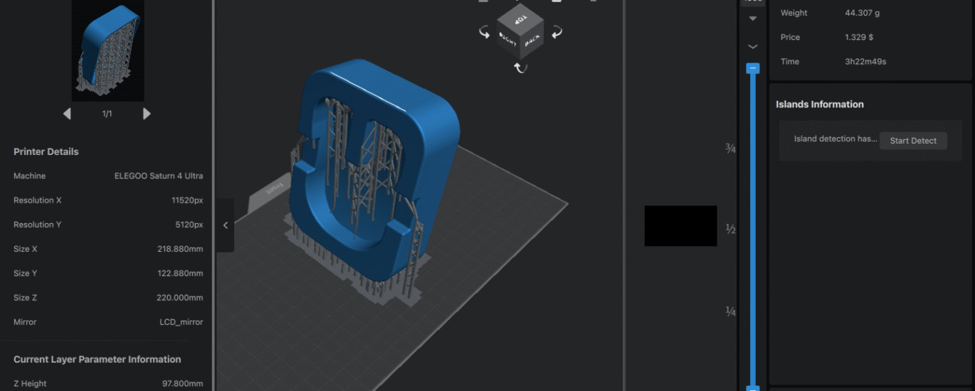
How your part is oriented on the build plate affects everything: surface finish, accuracy, support requirements, and print time. Here’s how to choose the best orientation:
Minimize Support Material: Orient your part to reduce overhanging features that require support structures. Supports leave marks on surfaces and require post-processing time.
Prioritize Critical Surfaces: Position your most important surfaces facing upward when possible. The top surface of each layer typically has the best finish quality.
Consider Layer Adhesion: The strongest direction in a 3D printed part is perpendicular to the layer lines. Orient parts so that primary stresses don’t try to separate layers.
Real-world Example: A custom phone case should be printed with the back face down on the build plate. This orientation eliminates supports inside the case, puts the visible outer surface facing up for best finish, and aligns the layer lines with the direction of stress when the case is flexed.
2. Wall Thickness Guidelines
Minimum Wall Thickness
Resin 3D printing can produce incredibly thin walls, but there are practical limits:
- Minimum recommended thickness: 0.4mm
- For functional parts: 0.8mm or thicker
- For decorative items: 0.3mm minimum
Avoid Ultra-Thin Walls
Walls thinner than 0.3mm may not cure properly and can break during cleaning or handling. If your design requires thin walls, consider:
- Adding ribs or support structures
- Creating a mesh or lattice pattern instead of solid thin walls
- Using flexible resin for parts that need to bend
3. Support Structure Considerations
45-Degree Rule
Any overhang greater than 45 degrees from vertical will likely need support. However, this doesn’t mean you should avoid overhangs – just design them thoughtfully:
Self-Supporting Angles: Features angled less than 45 degrees from vertical can often print without supports.
Bridging Capabilities: Short horizontal spans (under 5mm) can often bridge successfully without support.
Support-Friendly Design: When supports are necessary, design attachment points that are easy to clean up. Small contact points are easier to remove than large flat surfaces.
Specific Design Features
Holes and Circular Features
Vertical vs. Horizontal Holes
- Vertical holes (parallel to build direction) print with excellent accuracy
- Horizontal holes often print smaller than designed and may have poor surface finish
- For critical horizontal holes, design them 0.1-0.2mm larger than needed
Teardrop Modification
For horizontal holes that must be precise, use a “teardrop” shape – circular on the bottom with a pointed top. This eliminates the need for supports while maintaining functionality.
Threading and Screw Features
Printable Threads
3D printing can produce functional threads, but design considerations apply:
- Minimum thread pitch: 0.8mm
- Add 0.1-0.2mm clearance to threaded holes
- Coarser threads work better than fine threads
- Consider post-processing with a tap for critical applications
Alternative Fastening Methods
Instead of traditional threads, consider:
- Snap-fit features that flex during assembly
- Bayonet-style twist-lock connections
- Press-fit joints with slight interference
Snap-Fit and Living Hinges
Designing Snap-Fits
Snap-fit features take advantage of the flexibility possible with 3D printing:
- Design cantilever beams that deflect during assembly
- Include chamfered entry features for easy assembly
- Consider the deflection limits of your chosen material
Living Hinges
Thin sections that act as hinges can be printed in place:
- Typical thickness: 0.2-0.4mm
- Orient the hinge line perpendicular to build layers
- Test prototypes to find the optimal thickness for your application
Optimizing for Different Applications
Prototypes vs. Functional Parts
Prototype Priorities
- Focus on form and fit rather than ultimate strength
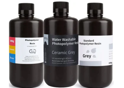
- Use standard resins for cost-effectiveness
- Accept some compromises in durability for faster iteration
Functional Part Priorities
- Choose engineering resins for strength and durability
- Design for stress concentrations and fatigue loading
- Include features for maintenance and replacement
Assembly Considerations
Clearances and Tolerances
3D printing accuracy is excellent, but not perfect. Design appropriate clearances:
- Sliding fits: 0.1-0.2mm clearance
- Press fits: 0.05-0.1mm interference
- Rotating joints: 0.15-0.3mm clearance
Assembly Sequence
Consider how parts will be assembled:
- Can all components be accessed during assembly?
- Are fasteners reachable with standard tools?
- Can the assembly be disassembled for maintenance?
Surface Finish Optimization
Layer Line Management
Minimizing Visible Layer Lines
- Orient critical surfaces perpendicular to build direction when possible
- Use smaller layer heights for surfaces that will be highly visible
- Consider the viewing angle – layer lines are most visible when viewed parallel to the build direction
Post-Processing Planning
Design for Finishing
- Include material allowance if parts will be sanded or machined
- Avoid deep recesses that are difficult to access for finishing
- Consider how support removal will affect surface finish
Common Design Mistakes to Avoid
Overhangs and Supports
Mistake: Designing large flat overhangs that require extensive supports Solution: Break large overhangs into smaller sections or angle them to be self-supporting
Wall Thickness Issues
Mistake: Using inconsistent wall thickness that leads to uneven curing Solution: Maintain consistent wall thickness throughout the design, or use gradual transitions
Trapped Uncured Resin
Mistake: Creating closed hollow spaces with no drainage Solution: Always include drainage holes in hollow parts, minimum 3mm diameter
Sharp Internal Corners
Mistake: Using sharp 90-degree internal corners that create stress concentrations Solution: Add fillets or radii to internal corners, especially in functional parts
Advanced Design Techniques
Lattice Structures
Weight Reduction: Internal lattice structures can reduce material usage while maintaining strength Design Guidelines: Use lattice cell sizes of 2-5mm for best results Applications: Ideal for parts where weight reduction is critical
Variable Wall Thickness
Optimization Strategy: Use thicker walls where strength is needed, thinner walls where weight savings matter Implementation: Modern CAD software can optimize wall thickness automatically based on stress analysis
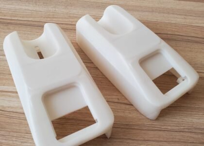
Multi-Part Assemblies
Design Strategy: Complex parts can be designed as assemblies of smaller components Benefits: Easier printing, better surface finish on critical faces, simplified repairs Considerations: Plan joint lines carefully and consider assembly time
Design Validation
Virtual Testing
CAD Analysis: Use built-in analysis tools to check for stress concentrations, interference fits, and motion studies 3D Printing Simulation: Some software can predict support requirements and potential print failures
Physical Testing
Prototype Early: Print test pieces to validate key features before committing to the full design Iterative Approach: Use rapid iteration to test different approaches to challenging features User Testing: Get parts into the hands of users early to identify design issues
Software Tools and Resources
CAD Software Recommendations
Beginner-Friendly: Tinkercad, Fusion 360 (free for personal use) Professional: SolidWorks, Inventor, Fusion 360 Professional Specialized: Rhino for organic shapes, OpenSCAD for parametric design
Design Rule Checking
Many CAD programs include design rule checking for 3D printing:
- Wall thickness analysis
- Overhang detection
- Support prediction
- Printability assessment
Working with 3D Printing Services
Communication is Key
When working with a 3D printing service like us, provide:
- Clear specifications for critical dimensions
- Information about the part’s intended use
- Any special finishing requirements
- Quantity needed and timeline
Design Review Services
Many printing services offer design review:
- Optimization suggestions for better printability
- Material recommendations based on application
- Cost reduction opportunities
- Alternative design approaches
Conclusion
Good 3D printing design is a balance of understanding the process capabilities, material properties, and application requirements. The tips outlined here will help you create designs that print successfully, function as intended, and look professional.
Remember that 3D printing design is learned through practice. Start with simple parts and gradually take on more complex challenges as you build experience. Each project teaches valuable lessons that apply to future designs.
The most important advice is to embrace the iterative nature of design and 3D printing. The low cost and quick turnaround of 3D printing make it easy to test ideas, learn from failures, and continuously improve your designs.
Whether you’re designing your first 3D printed part or your hundredth, following these guidelines will help ensure successful results and efficient use of both your time and resources.